Overview

This is a guide for building a DIY power supply/regulator for powering a Raspberry Pi and a USB audio output interface. The objective is to create a pure, regulated 5.0v power supply that allows the Raspberry Pi to run stably but also, more importantly, allows the USB audio device to avoid creating jitter in the digital audio signal.
This design is adapted and expanded upon from an article on the raspyfi.com project page.
A listening setup made up of this power supply unit, a Raspberry Pi, a USB audio interface (and/or DAC), and the Volumio Linux distro and music playback software forms an audio chain that can create hi-fidelity, bit-perfect audio. This is all accomplished using free software and inexpensive hardware, providing incredible value for the hi-fi audio enthusiast. Check out the Volumio project page and forum for all the goodness.
Demo
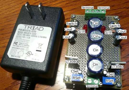
Circuit

Design
In a nutshell, this design provides two high-quality 5.0V regulated power rails from an inexpensive 7.5V DC wall adaptor. One rail is intended to to power the Raspberry Pi and one is intended to power a USB audio output accessory. Each rail has its own independent LT3080 linear regulator and its own independent output capacitance.
This is the basic intended circuit for the LT3080:

Our circuit uses the 7.5V adaptor as Vin, adds a lot of input and output capacitance, and uses an optional capacitor across Rset to improve the noise and transient responses of the output. Rset is precisely set with a trimmer resistor to produce an exact 5.0V output voltage (5.0V being what is needed to power a USB device).
Enemy 1 – Power supply ripple

Pretty much All AC-to-DC power supplies will exhibit voltage ripple. Particularly when we are using low-cost hardware, like the Raspberry Pi, one is less inclined to pay money for a higher-quality power supply without apparent benefit. Generally, any inexpensive wall adaptor will have a ripple of 120Hz with some detectable amplitude that is problematic for hi-fi digital audio.
When producing a digital audio signal that is of 44.1kHz (CD quality) or higher, these ripples can have an effect on the oscillator which can result in digital audio signal jitter. This signal jitter can then affect the digital-to-analog conversion process resulting in imperfect sound reproduction.
The chosen 7.5V wall adaptor certainly has ripple in it that needs to be dealt with. In this design, this is done by two mechanisms. First, by using a linear regulator, the ripple can be minimized. The LT3080 datasheet promises 70dB of ripple rejection for current loads of 200mA. Second, the input capacitors will have a dampening effect on voltage change, resulting in additional ripple rejection.
Enemy 2 – Power supply transient voltage changes
A big concern is that the Raspberry Pi’s current draw can wildly fluctuate when operating. It is reported to idle at about 360mA, and can go as high as 800mA depending on what hardware is in use and what is going on in the system at the time. These changes in load can cause temporary deviations in the voltage out of the power supply. This unstable voltage can negatively affect digital audio signal quality the same as ripple voltage.
For an illustration of what can happen to the voltage under changing load current, there is this graph provided in the LT3080 datasheet:

To combat this effect, first, the LT3080 helps manage the load transient response for the Raspberry Pi. This alone will be better than just a cheap 5.0V DC power supply alternative. Second, the output capacitance of 440uF, along with the Raspberry Pi’s C6 Capacitor provides a total of 660uF to smooth the voltage deviation from Raspberry Pi’s load. Third, the use of an optional capacitor across the SET resistor of 1.0uF improves the regulation of the LT3080.
Enemy 3 – Multiple devices sharing a power supply
Normally, a USB sound device would be plugged into the USB port of the Raspberry Pi and the power for that device would be drawn from the 5.0V USB pin. When the devices share a power source, they are going to share transient voltage changes. Since the Raspberry Pi is particularly bad for transient voltage changes, we want the audio device powering voltage to come from a second regulated supply.
In this design, the 5.0V power pin for the USB audio device is not connected to the Raspberry Pi, but rather to second rail of our power supply regulator. This rail has its own linear regulator and its own output capacitance to keep this voltage mostly independent from the variations in the Raspberry Pi’s voltage.
It is not perfectly independent, however. As the current draw on the Raspberry Pi changes, this will have an effect on the current draw on the input DC causing a small deviation in the wall adaptor’s voltage (it is, after all, a cheap power supply). Since this voltage is used as input on the second rail’s linear regulator, the effect from the Raspberry Pi’s transience will have an effect on that second rail. Viewed from the perspective of the second LT3080 regulator, the input voltage deviation is called a ‘line transient’. From the LT3080 datasheet, there is an illustrative graph to show what can happen to the output voltage in the presence of a line transient:

This effect is addressed by, first, having a large amount of input capacitance to dampen the input voltage change. Second, the use of an optional capacitor across the SET resistor of 1.0uF helps improve the regulator’s transient performance. Third, the 440uF of output capacitance for the second rail will also help output voltage stability.
Of course, this relationship between the two rails also applies the reverse direction if the USB audio device’s load changes. However, in practice, I have observed that the USB audio device I am using doesn’t draw as much current as the Raspberry Pi, and the current draw appears to be pretty much stable throughout operation.
Enemy 4 – Heat generated by the regulator
According to the LT3080 datasheet, one can calculate the power consumption of the regulator as:
Ptotal = Pdrive + Poutput
For the Rasberry Pi rail:
Pdrive = (Vcontrol – Vout) * (Icontrol)
Icontrol = Iout / 60
Poutput = (Vin – Vout) * (Iout)
Vin = Vcontrol = 7.75V
Vout = 5.0V
Iout (maximum) = 0.8A
So,
Poutput = (7.75V – 5.0V) * (0.8A / 60) + (7.75V – 5.0V) * 0.8A
Poutput = 2.2367W = Maximum power dissipation
Repeating the calculation for the idle current of 360mA, which should be closer to typical current draw for playing music on the Raspberry Pi.
Poutput = 1.0065W = Typical power dissipation
The datasheet gives a rough calculation for what can be expected for junction temperature as a function of power and ambient temperature:
Since we are using the T package of the LT3080, the dissipation (θja) is listed as 40°C/W.
Assuming a maximum ambient temperature of 50°C:
Max Junction Temp = 50°C + 2.2367W * 40°C/W
Max Junction Temp = 139.468°C
This is very hot, however, it is unlikely that we will be operating in these conditions. If we assume 25°C as the ambient and the Poutput as the assumed-typical 1.0065W, we get:
Typical Junction Temp = 65.26°C
The datasheet does show how the regulator changes behaviour based on temperature along a few different dimensions. However, none of them particularly relate to the regulation response. This indicates that we could maybe get away with not having any cooling, but it risks burning up your components on a hot day or burning your hand if you touch it. A little bit of cooling is the smart choice. Included in the part lists are some small heat sinks that are clamped to the linear regulator (with ugly binder clips for now). In practice, I find that after playing music for 10 minutes, the heat sinks are definitely warm, but not hot enough to burn a finger or cause much discomfort. I would estimate it as above body temperature (37°C), but definitely below the calculated 65°C (as would be expected).
For the second rail, with my USB audio device as the load, with one small heat sink on the regulator, the temperature barely registers as lukewarm after similar use. I would estimate it as at or below body temperature (37°C).
Enemy 5 – Start up undervoltage

Since we are loading up this power supply with a lot of capacitance and also choosing to use a capacitor across the SET resistor, we are getting a circuit that takes at least a second or two to reach 5.0V upon powering it on. This time is needed for the capacitors to charge up and for the SET resistor current to stabilize.
If this circuit is turned on while directly connected to the Raspberry Pi and the USB audio device, one can see the LEDs on these boards gradually get brighter as the voltage rises. This is really not good for the electronics and can cause software stability problems during or after boot.
To avoid this problem, this circuit has two stages of switches. The first stage is the switch on the input voltage for convenience of turning the board off and on without having to plug and unplug the wall adaptor. The second stage is a switch for each of the the output terminals. The first stage can be switched on to allow the capacitors to charge and for 5.0V to be reached. The output LEDs on the board can be watched to see when they have stabilized to full brightness. Once this is complete, the second-stage switches can be turned on to boot the Raspberry Pi and audio unit.
To turn the system off, this can be done in reverse, turning off the load devices first, and then cutting off the input voltage. The discharge of the capacitors can be observed by the decaying brightness of the LEDs.
This is indeed a small bit of manual effort to power the system on and off each time, but it is a small price to pay for sweet sound. 😉
Components
Linear voltage regulators
- Linear Technology LT3080 T package
- The T package is definitely recommended to help with heat dissipation
- $5.02 CAD each
- 2 are required for this design

This is the centrepiece of this circuit. The datasheet is the primary reference for how to properly set up a circuit around it. If you are interested in the kind of thing, or wish to learn more about this kind of circuit I would recommend a deep dive into that document.
This part was recommended in the raspyfi.com article. It is ideal for a USB power supply in that it allows up to 1.1A of output (the USB standard limits maximum current draw to 0.9A). To be honest, I didn’t spend much time investigating any alternatives, but I am sure there are perfectly good ones out there.
7.5V AC-to-DC Wall Adaptor
- Used for the input voltage
- Triad Magnetics 7.5V 3.2A power supply
- $16.30 CAD each
This wall adaptor provides the input voltage to the regulator. When plugged in, it measures 7.75V on my multimeter. 7.75V is above the target output of 5.0V, but not so much that the power dissipation is excessive (P = I * Vdrop). This power supply is rated for 3.2A, which should be sufficient for the two USB devices which shouldn’t need more than 1.8A altogether (0.9A being the allowed maximum per device).
Note that there are similar power supplies that output 6.0V, but this is an insufficient voltage to regulate at 5.0V using the LT3080 and this design. According to the datasheet, Vcontrol has to be 1.3V to 1.6V greater than the desired Vout. Since, in this design, we are connecting Vin to Vcontrol, this input voltage must be 6.6V or higher to be able to regulate at 5.0V.
An alternate design could use a 6.0V or lower input voltage to target 5.0V, but would need to provide a separate Vcontrol of 6.6V or higher. This would require a second voltage source but, on the upside, it would have advantages when it comes to heat dissipation.
Project Board
- Vector Electronics 2″ x 3″ perforated board
- $7.15 CAD
I chose this board mainly because it had the corner holes for the hex spacers, and it seemed to be the right size for this circuit. As for ease of soldering the parts on, I have no complaints. The spacing of the holes on this board is 5.08mm, which is important to pay attention to for choosing some of the other parts (notably, the terminal blocks and the trimmer resistor).
2200uF capacitors
- used for Cin
- Panasonic 2200uF 16V Aluminum Capacitor
- $0.84 CAD each
- 4 or 5 are required for this design
- I chose 4, but I could have comfortably fit 5 on the project board
I chose this particular capacitor because they are relatively small and relatively cheap. In parallel, four of them makes for a total of 8800uF input capacitance
Trimmer resistors
- used for Rset
- Bourns Inc. 1M Ohms trimmer
- $3.16 CAD each
- 2 are required for this design
According to the LT3080 datasheet, the output voltage is determined by this resistor (Vout = Rset * 10uA). Hence, for a 5.0V output, 500kOhms of resistance is needed. A variable trimmer resistor like this allows the voltage to be precisely set by measurement and adjustment. Since this is a 1000kOhm resistor, it needs to be dialled to the middle of the adjustable range.
Be sure to get a trimmer that has pins that match the hole spacing of your project board. This particular part has spacing that matches the 5.08mm project board I chose.
1.0uF Capacitors
- Used for Cset
- Panasonic 1.0uF 50v Aluminium Capacitor
- $0.40 CAD each
- 2 are required for this design
Using a capacitor across the SET resistor is optional according to the LT3080 datasheet. However, it is recommended for improving transient response and reducing system noise. This is a huge win for our application. The drawback is that the start-up time of the output voltage can lengthened. The datasheet also mentions (on page 10) that for Cset “Capacitors up to 1uF can be used.” For this application, we might as well go with the maximum.
220uF Capacitors
- used for Cout
- Panasonic 220uF 16V Aluminium Capacitor
- $0.56 CAD each
- 2 are required for this design
- I chose to use 4, but more or larger capacitors are a valid choice
For the LT3080, 2.2uF is the minimum required for Cout. From learning a bit about the Raspberry Pi design, I have observed that a 220uF capacitor was used across the input to help stabilize the input voltage. The choice of 440uF for Cout triples that capacitance. For the USB audio device rail, 440uF is also deemed sufficient, since the power requirements are less than the Raspberry Pi. A choice of an even higher capacitance may improve the regulation performance slightly, but would lengthen the start-up time.
LEDs
- Used for minimum load
- Everlight Electronics 2V 200mA 5mm Red LED
- $0.53 CAD each
- 2 are required for this design
The datasheet for the LT3080 specified that a minimum load current of 0.5mA is needed for voltage regulation. One of these LEDs with a 2.2kOhm resistor will draw a current of approximately 1.5mA while lighting up the LED to a reasonable brightness. With this current always flowing, the regulator will always be within the functional range regardless of whether the
real load is switched on or not.
These LEDs also serve the purpose of giving a visual indication of the voltage currently on the circuit by their relative brightness. This can help during start-up to show that the capacitors are ready before turning on the second switches. For powering off, these can also help to slowly discharge the capacitors and give a visual indication of this discharge process. This can also be considered a safety feature as it can avoid a risk of accidental electric shock if some handling of the circuit is needed after powering off.
The link above that has the price listed as $0.53 each is quite expensive. I got a bag of 10 LEDs from my local electronics shop for $0.88.
2.2kOhm Resistors
- used for minimum load
- Yageo 2.2kOhm Resistor
- $0.23 CAD each
- 2 are required for this design
These are used in conjunction the LEDs to provide the 1.5mA minimum load current. Again, the linked price is expensive. Resistors are very cheap if you buy them in bulk and don’t mind having them lying around.
Toggle switches
- E-Switch 5A 120V
- $2.41 CAD Each
- 3 are required for this design
These are used for the two stages of switches. The first stage is on the input voltage and is mainly for convenience. The second stage is on the output voltage on each of the rails to make sure the power supply is regulating up to 5.0Vs before turning on the Raspberry Pi and audio board.
Also, powering the Raspberry Pi on and off via a crisp toggle switch as opposed to plugging/unplugging the micro USB connector feels very nice. 😉
I didn’t use the linked switches. I got mine from my local electronics shop where they were in a bag of 10 for $13. Aside from the colour, they appear equivalent to the one linked above.
Wire-to-board terminal blocks
- Phoenix Contact 2POS 5.08mm Terminal Block
- $1.07 CAD each
- 3 are required for this design
Audiophile purists might insist on soldering the input/output wires directly to the board for the cleanest electrical connections. I chose wire-clamping terminal blocks since it allows a bit of flexibility while I tinker around with this setup and it allows easier testing of the voltage via touching a multimeter to the top screws. For the output terminal of four wire connectors, these blocks of two snap together via a small plastic fitting to make a row of four.
Heat sinks
- Assmann 1cm x 1cm aluminium heat sink
- $0.80 CAD each
- 3 are required for this design
On the Raspberry Pi rail, I need two of these heat sinks clamped to the LT3080’s metal tab in order for the temperature to be stable. To hold them on, I am using a simple binder clip that I had in my drawer.
While it does the job, this is a bit awkward and I am searching for a different heat sink setup. A better aluminium or copper heat sink could probably be salvaged from some old, discarded electronics.
For the audio device rail, I only have one clamped on and the temperature is pretty much negligible. However, the results might be different depending on what kind of load you end up using.
Layout & Soldering


Part Cost
|-----------------------------------------------|
| Item                | # | Each  | Total       |
|-----------------------------------------------|
| 7.5v Wall Adapter   | 1 | 16.30 | 16.30       |
| Prototype Board     | 1 |  7.15 |  7.15       |
| Terminal Blocks     | 3 |  1.07 |  3.21       |
| LT3080              | 2 |  5.02 | 10.04       |
| Trimmer Resistor    | 2 |  3.16 |  6.32       |
| Switch              | 3 |  2.41 |  7.23       |
| LED                 | 2 |  0.54 |  1.08       |
| 2200kOhm Resistor   | 2 |  0.23 |  0.46       |
| 2200uF Capacitor    | 4 |  0.84 |  3.36       |
| 220uF Capacitor     | 4 |  0.56 |  2.24       |
| 1.0uF Capacitor     | 2 |  0.40 |  0.80       |
| Heat Sink           | 3 |  0.80 |  2.40       |
|-----------------------------------------------|
| Total Part Cost                 | 60.59       |
| Tax (Alberta)                   |  3.03       |
| Shipping                        |  8.00       |
|-----------------------------------------------|
| Total                           | $71.62 CAD  |
|-----------------------------------------------|

Other Misc. Costs (local hardware store):
----------------------------------------
* Binder clips for heat sink
* Mounting surface (I used a sheet metal
    "duct cover" bought at Home Depot)
* Hex spacers
* Hex spacer screws
* Solder
* Wires
----------------------------------------
Total Misc: About $5-$10 CAD in all
Grand Total = approximately $80 CAD as built

Thanks for this!
I just ordered the necessary parts.
Can’t wait for them to arrive.
Cheers
Hi, very cool. What about a delay relay for the startup undervoltage prevalent in many audio devices? I am not an expert, but what if when voltage reaches say 4.7v (or minimum specs for Raspberry voltage) at the 2x220uF capacitors a transistor triggers a relay with double output that connect both circuits. The relay would also cut the voltage more abruptly when disconnecting. It will probably cost less than $10 for the relay, transistor, couple of resistors and diode if kept simple. Do you see any complications or improvements?
I can’t say I am an expert either. I don’t have any experience with using a relay like this. It is kind of annoying to have to wait for the voltage to settle before switching the Pi on. If you experiment wtih this, I would definitely be interested to see the results.
google “delay relay for amp” for images and you will see circuit diagrams (1 transistor, 1 res, 1 cap, 1 diode, 1 relay). The idea is to delay connecting the speakers in an amp to avoid them producing a loud pop noise, but can be easily adapted to provide power to RPi2 and other circuits. Or check for “5v delay relay module” in ebay for assembled boards.
How much would a Bel Power Solutions HB5-3/OVP-AG cost in Canada? It’s a Power-One 5VDC @ 3ADC Linear Power Supply, and costs ~$58 USD, from Allied Electronics.
The toggle switch on the link does not fit the circuitboard. Which one did you use?
I used one pretty much exactly like the one in the link. I had to drill a hole in the board at the right diameter for the switch. Sorry if that was not clear.
Hi, cool stuff.
I have a project where I’ll be using a Rasp Pi 3b and hifiberry dac pro
They stack, so I need to know how to go about powering them separately (usually the hifiberry is powered by the pi directly) Can you point me in the right direction?
second – rather than a power brick transformer, I’d like to have a 240plug on the back and then have a transformer / power supply internal to the case I am building my project in.
How practical is that? Can you suggest parts or an off-the-shelf (inexpensive) solution for this?
Thanks
I am thinking of replicating this design to output 5v for rpi and 7.5v for Allo DAC.
I was thinking of swapping LT3080 for TI UCC283, datasheet: http://www.ti.com/lit/pdf/slus215
This will allow me to create the 2.5A / 3A needed at 7.5v for the DAC.
My concern is ripple rejection doesn’t seem great. Any thoughts?